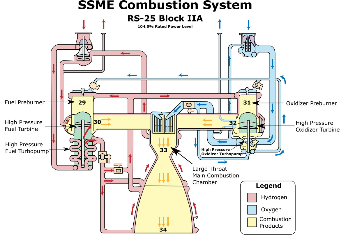
Figure 1.3.1: SSME Combustion System Schematic [1, 2]
The SSME Combustion System performs three functions:
a. Power the SSME Fuel System.
b. Power the SSME Oxidizer System.
c. Generate thrust by expelling combustion products from the nozzle.
Hydrogen and oxygen enter the Fuel Preburner at Station 29. In this chamber the propellants are mixed and combusted to form a hot gas consisting of approximately 90% hydrogen and 10% water vapor by mole fraction (shown in yellow on Figure 1.3.1). This mixture flows through the blades of the High Pressure Fuel Turbine and departs at Station 30. This causes the turbine blades to spin, which in turn causes the rotors in the High Pressure Fuel Turbopump to spin due to the shaft connecting them. This process powers the entire SSME Fuel System.
The SSME Oxidizer System is powered in a similar manner. Hydrogen and oxygen enter the Oxidizer Preburner at Station 31. In this chamber the propellants are mixed and combusted to form a hot gas consisting of approximately 90% hydrogen and 10% water vapor by mole fraction (shown in yellow on Figure 1.3). This mixture flows through the blades of the High Pressure Oxidizer Turbine departs the turbine at Station 32. This causes the turbine blades to spin, which in turn causes the rotors in the High Pressure Oxidizer Turbopump and the Preburner Oxidizer Booster Pump to spin due to their mechanical linkage. This process powers the entire SSME Oxidizer System.
After departing the high pressure turbines at Stations 30 and 32, the resulting gas mixtures are routed to the Large Throat Main Combustion Chamber (LTMCC) at Station 33 . It is important to note that the gas mixture entering the LTMCC consists of approximately 90% hydrogen by mole fraction. This composition contains sufficient hydrogen to combust yet again when combined with the oxygen flowing in to the LTMCC from the powerhead. The resulting chemical reaction creates a gas mixture at 6000 °F that is approximately 65% water vapor by mole fraction. This mixture accelerates through the throat and down the nozzle, trading its thermal energy for kinetic energy. By the time the gas reaches the nozzle exit plane at Station 34, it has accelerated to Mach 4.54 which enables the SSME to produce approximately 490,000 pounds of thrust (in vacuum conditions).
Table 1.3 displays several key thermodynamic properties of the flow as it progresses through these stations. The mass flow rates, temperatures, and pressures listed below were tabulated from Reference [2]. Densities and enthalpies were calculated utilizing combustion model described in Section 2.4, and the turbine model described in Section 4.2. “Frozen flow” is assumed for combustion product composition. (i.e. composition remains fixed after combustion is complete).
Overall SSME Performance Data
| Sea Level | Vacuum | |
|---|---|---|
| Nozzle Exit Velocity [m/s] | 4311 | 4311 |
| Thrust [lb] | 398,400 | 491,900 |
| Specific Impulse [s] | 366 | 452 |
| Station | Component | Mass Flow $kg/sec$ | Temp $K$ | Pressure $MPa$ | Density $kg/m^3$ | Enthalpy $kJ/kg$ |
|---|---|---|---|---|---|---|
| 29 | Fuel Preburner | 65.7 | 983 | 33.05 | 15.06 | -1496 |
| 30 | High Pressure Fuel Turbine Exit | 68.0 | 859 | 22.03 | 6.68 | -2346 |
| 31 | Oxidizer Preburner | 30.8 | 739 | 33.18 | 17.65 | -1708 |
| 32 | High Pressure Oxidizer Turbine Exit | 30.8 | 660 | 21.37 | 8.82 | -2366 |
| 33* | Large Throat Main Combustion Chamber (Throat Stagnation Conditions)* | 492.1 | 3589 | 19.79 | 8.64 | -260 |
| 34 | Nozzle Exit | 492.1 | 1150 | 0.02 | 0.027 | -8743 |
| Station | Component | Mass Flow $lbm/s$ |
Temperature $F$ |
Pressure $psi$ |
Density $lbm/ft^3$ |
Enthalpy $BTU/lbm$ |
|---|---|---|---|---|---|---|
| 29 | Fuel Preburner | 144 | 1309 | 4793 | 0.940 | -643 |
| 30 | High Pressure Fuel Turbine Exit | 150 | 1087 | 3195 | 0.417 | -1008 |
| 31 | Oxidizer Preburner | 68 | 871 | 4812 | 1.102 | -734 |
| 32 | High Pressure Oxidizer Turbine Exit | 68 | 728 | 3099 | 0.550 | -1017 |
| 33* | Large Throat Main Combustion Chamber (Throat Stagnation Conditions)* | 1085 | 6000 | 2871 | 0.540 | -112 |
| 34 | Nozzle Exit | 1085 | 1610 | 2.86 | 0.002 | -3759 |
| Station | Component | H | H2 | H2O | O | OH | O2 | Molecular Weight | Specific Heat Ratio |
|---|---|---|---|---|---|---|---|---|---|
| 29 | Fuel Preburner | 0 | 0.899 | 0.101 | 0 | 0 | 0 | 3.61 | 1.365 |
| 30 | High Pressure Fuel Turbine Exit | 0 | 0.899 | 0.101 | 0 | 0 | 0 | 3.61 | 1.365 |
| 31 | Oxidizer Preburner | 0 | 0.928 | 0.072 | 0 | 0 | 0 | 3.16 | 1.384 |
| 32 | High Pressure Oxidizer Turbine Exit | 0 | 0.928 | 0.072 | 0 | 0 | 0 | 3.16 | 1.384 |
| 33* | Large Throat Main Combustion Chamber | 0.0282 | 0.2517 | 0.6724 | 0.0041 | 0.036 | 0.0074 | 13.551 | 1.19346 |
| 34 | Nozzle Exit | 0.0282 | 0.2517 | 0.6724 | 0.0041 | 0.036 | 0.0074 | 13.551 | 1.19346 |
Table 1.3.1